Fine Tuning Part Design For Injection Molding
The solid model is complete, the quotes are in, the tooling order has been placed. What is there left to do? Fine tuning those minor details that won’t get addressed until tooling is being designed. Why wait until now to do this? No one wants to invest time in these technical issues until they know that another molder won’t benefit from their efforts.
Let’s start with the details that often aren’t included on the print and are never included on a solid model
Starting with the details that often get left off of a print, and never shown on a solid model:
What are the tolerances needed to fit mating parts? How flat does the part have to be? Some materials warp more than others. Is sink going to be an issue?
What are functional surfaces? Is a parting line going to interfere with function? What surface can the gate be positioned, and do the knock out pins(with eventual flash) hinder function? What are seal surfaces? Does the part need to be void free, or can some level of porosity be allowed?
- KO Pins Flush to .005 below surface
- No Flash
- Tolerance ± .005
- (X.xxx) ± .010 (X.xx)
- Color: Grey (Pantone XXX)
- Surface Finish: SPE #B-2
“No flash allowed” is not realistic
A common note on a print is “no flash allowed” which is an impractical wish. You might not see it, or measure it, but it will always exist at the parting line, or insert witness line. An “O Ring recess” will always leak if there is a witness line perpendicular to the diameter. A witness line following the O ring diameter might actually improve sealing.
The color is noted on the print as gray. Is it a specific pantone color, or can the molder use existing colorants? Is the color critical to match other mating parts?
Has the amount of regrind been considered? Some materials like PEI, 6/6 nylons, HIPS, and ABS can use considerable amounts of regrind. Some molders believe 100% recycled 6/6 nylon actually runs better than virgin pellets. There may be a color shift, or more black specs (which also might be defined) with increasing amounts of regrind. Other materials (such as POM) really shouldn’t use more than 25% regrind as a general rule.
While there are a lot of questions, there are a lot of answers. The answers will vary depending upon the experience of the molder, and by experience gathered by years of overcoming diverse issues.
Gates are a requirement on an injection molded part
Gates are where molten plastic enters the cavity of the mold. When a molder starts considering the ideal location, there are many variables. The first being appearance, the second is where will the weld line (and inherent weakness) and subsequent venting, cause the least issue? How long is the flow length relative to part thickness? Gates should be located to provide thick to thin melt flow to reduce sinks and minimize warp. Solidification of the hot plastic in the mold is thickness dependent, so you want flow to stop or slow down towards the gate, keeping pressure in the still molten areas.
Gates should be directed towards a feature in the cavity which will impede flow and prevent jetting which is an uncontrolled “squirting” of plastic across the cavity leaving a rough surface that looks like a worm. A long flow length, with thin walls will mean greater warp with some crystalline materials such as nylon, than with amorphous materials such as ABS, but warp will exist in both.
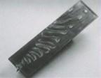
Differential mold temperatures are one way of mitigating this warp, but not always. Machining the gate is an expensive option, but sometimes is the best solution. Such as when no weld lines can be tolerated, 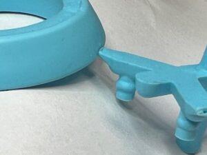 or with a fiber filled material such as PEEK on a bearing where roundness is critical. Subgates degate automatically and are preferred by molders. A blemish on the outside of the part is a result, just as edge gates leave a blemish. (See picture.)
Many years ago, when an operator used to be at every machine, they would cut the edge gates by hand with a pair of cutters. At Recto we had a lot of edge gates which we converted over time to subgates, getting the operators away from machines to do more meaningful work. But subgates stick in the mold sometimes and it wasn’t unusual to be running 14 cavities of a 16 cavity mold after a few days. Subgates wear faster with glass filled materials, and are more fragile. With the proliferation of 6-axis robots at Recto, edge gates with their inherent advantages have become more viable.
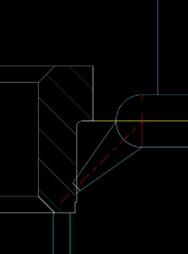
Methods for ejecting from the mold
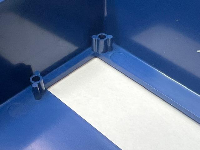
Knockout pins, sleeve knockouts, blades, lifters, stripper plates all are used to eject the hot molded part from the mold. All knockout methods share the same rules: they need to push against the stiffest most constrained feature on the part and need to eject a soft(hot) plastic part evenly and quickly from the mold. More square inches of ejector pin always helps in this regard.
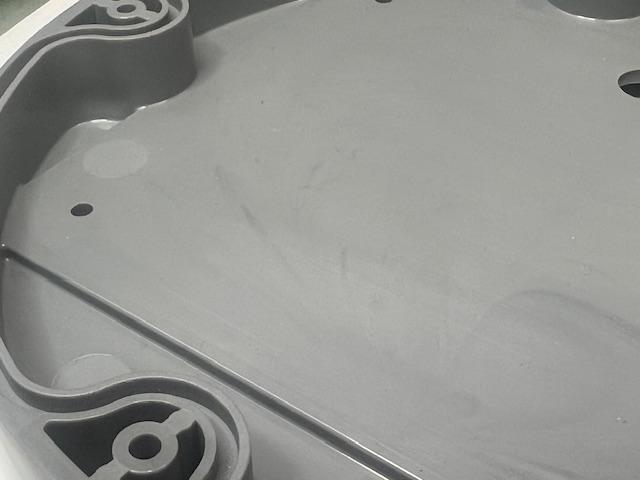
They also do a lot of venting, so at least one of them needs to be at the weld line. Standard knockout pins are the most common, and more rather than fewer is the rule. They are inexpensive, and easy to replace. The surrounding mold cools them. Using bosses on the part allows larger diameter pins to be used.  Sleeve knockouts are probably the second most common, they are around round core pins.
Here there is a trap. Because of the way molds are built, the core pin gets retained at the furthest side of the mold, (making them very long ) and if small in diameter are very hard to cool. Adding water to larger (bigger than ,250”) core pins works very well, but is now an area for potential water leaks if O Rings are used to seal the pin. Guided ejection is required to reduce long term wear since sleeves are especially susceptible to non-linear motions.
Blade knockouts are used as a last resort and used when they need to be very thin. They bend easily and getting the four corners of the blade to fit well into a rectangular opening in the mold is difficult making flash a concern. Lifters get used when there is an undercut on the part, and when they are beneficial in ejecting and preventing trapped walls. A concern here is to have a design where the part is constrained by a feature during ejection so the part doesn’t want to stick to a lifter. My favorite ejection system is a stripper plate. It is too bad they can’t be used more often. Easy to cool, can eject thin walls, venting is consistent, when designed with draft angles on cores have the best long term wear resistance and the core pin is easily cooled.
Surface finish
Is the surface of the part visual or functional? Usually finish is defined on the print, but sometimes it gets over looked. When the cavity building is done with CNC machining the surfaces need to be polished to get rid of cutter marks unless specified. In the past a quick way of telling if a mold was built offshore would be the cutter paths on the non-functional surfaces. Domestic toolmakers didn’t see that as an option. It became a criticism, and the off-shore toolmakers started polishing as well. A “paper” , meaning sand paper finish, is usually a default finish. When EDM is used to produce a feature in the mold, the oxide finish normally gets polished off, and a slight textured finish is the result. More polishing, results in better surface finishes. Some customers like the appearance of an EDM, low gloss surface. It hides molding defects. Parts that need a good surface finish get polished at a significant cost(time).
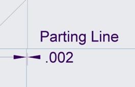 Intentional mismatch. Regarding witness lines and parting lines, when it is beneficial to intentionally make an area smaller than a mating surface for function, inspection, or long term flash control, the best time to do this is during mold design. When the stationary side(A side) of the mold is .002” / .003” smaller per side than the moving side of the mold(B side) it accommodates any parting line mismatch caused by incidental machining differences or wear on guide pins/bushings or side locks. It is a normal detail understood by experienced mold builders but should be planned for in advance. This same concept should be considered where there are features in the mold that are separate components such as cores, or core pins. Any surface that is non-functional should be recessed by .002/.003”.
